“An automation can expose multiple exit points (for example, Success and Failure) and can define output parameters that return values to the caller. When the automation completes, the appropriate exit point is raised and the output parameters are made available to the caller.”
“When one automation calls another, the called automation appears as a component with input parameters, output parameters, and exit points. The caller wires the Success/Failure exits to the next steps and maps output parameters (for example, result, errCode) to downstream logic.”
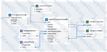
Why Option C is correct:
The UpdateCustomerDetails block in Option C clearly shows two exit points — Success and Failure — and two output parameters — result and errCode — on the subautomation.
The wiring demonstrates a typical pattern:
On Success, the flow proceeds to a success path with result available.
On Failure, the flow proceeds to a failure path with errCode available (the extra, unused result pin on the failure jump is permissible but not required).
This matches the specification precisely: two exits (Success/Failure) and two outputs (result, errCode).
Why the other options are not correct:
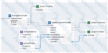
Option A: Shows errCode but does not expose result clearly as an output to the success path.
Option B: The component does not display errCode as an output parameter of the subautomation.
Option D: Emphasizes an additional boolean/conditional output and maps result on the failure path, which does not reflect the stated definition of the subautomation outputs.
Document Sources (Exact Extracts Reference):
Pega Robotics Studio User Guide — Automation Design Concepts: Entry/Exit Points and Parameters.
Pega Robotics Studio User Guide — Calling Automations and Mapping Inputs/Outputs.
Pega Robotics System Certification Study Material — Subautomation design patterns (Success/Failure with output parameters).