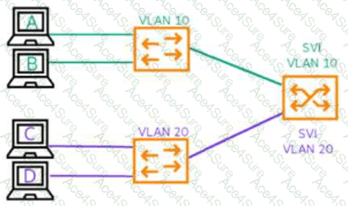
How many collision domains are shown in the diagram below?
A.
1
B.
2
C.
3
D.
6
The Answer Is:
D
This question includes an explanation.
Explanation:
The correct answer is D. 6. In a switched Ethernet network, each individual switch link or switch port represents a separate collision domain. The diagram shows four end-user device links: PC-A to the VLAN 10 access switch, PC-B to the VLAN 10 access switch, PC-C to the VLAN 20 access switch, and PC-D to the VLAN 20 access switch. It also shows two uplinks from the access switches to the Layer 3 switch or routing switch that contains the SVIs for VLAN 10 and VLAN 20. That gives a total of six physical Ethernet links, and therefore six collision domains. The VLANs do not reduce this count to two; VLANs define Layer 2 broadcast domains, not collision domains. The SVIs also do not create one collision domain; they are Layer 3 gateway interfaces used for routing between VLANs. HPE Aruba Networking campus design documentation describes Layer 2 and Layer 3 switching technologies used in campus topologies, while HPE Aruba switch documentation treats physical switch ports as individual Ethernet interfaces. For this diagram, the collision-domain count is based on the physical switched links, so the answer is 6.
HPE6-A86 PDF/Engine
Printable Format
Value of Money
100% Pass Assurance
Verified Answers
Researched by Industry Experts
Based on Real Exams Scenarios
100% Real Questions
Get 65% Discount on All Products,
Use Coupon: "ac4s65"