In the CSI Uniform Drawing System (UDS), now incorporated into the National CAD Standard, specific symbols are defined to link one drawing to another and to distinguish between types of referenced views (sections, details, elevations, etc.).
An elevation reference symbol placed in a plan view:
Identifies that an elevation drawing exists elsewhere,
Indicates which elevation it is (view or detail number), and
Indicates on which sheet that elevation is drawn.
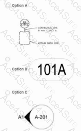
The typical UDS elevation callout symbol is a circle with a pointer/triangle indicating the direction of view, with two fields of text: the view or detail identifier (e.g., “A1”) and the sheet number (e.g., “A-201”). That matches Option C: a circular symbol, with a black “wedge” or triangular pointer indicating the direction the elevation is looking, text such as “A1” near the pointer, and “A-201” within or adjacent to the circle showing the sheet where the elevation view is found.
Why the other options are incorrect:
Option A – This resembles a detail/section marker or a generic callout with line-type notes, not the standard UDS symbol for an elevation view referenced from plan.
Option B – An oval with “101A” is characteristic of a room or space tag (identifying room number, sometimes with occupancy or area), not a cross-reference to another drawing. It does not direct the user to any elevation view.
Option D – The small cross with a leader to a rectangle labeled “EL” is the UDS-type symbol for a spot elevation or elevation note, giving the vertical level of a specific point (e.g., top of slab at Elev. 103.50). It indicates a numeric elevation value, not a separate elevation drawing elsewhere in the set.
According to CSI’s UDS, the symbol used in plan that directs the user to an elevation view on another sheet is the elevation reference/callout symbol, represented by Option C.